Summary
Pursuant to the requirements of DAGCAP SOP-4 v1.0 Software Validation, this document provides default input parameters for AGC processing in BTField, and guidance on when to change them, how changing them impacts the results, and documents limitations of the software.
The use of BTField on projects falling under DAGCAP is restricted to the list of approved AGC sensors on the DENIX website. BTField should not be used for AGC where analysis of available data indicates targets of interest cannot be reliably classified due to site-specific conditions (e.g. elevated EM noise, magnetic soil response, etc.). These limitations may apply to certain areas of a site, in which case they should be documented in the appropriate deliverable (e.g. Data Usability Assessment).
We will describe the BTField default settings for each of the following processing steps:
1) MQO validation of Function Tests
4) Running the Auto-Invert Flow
5) MQO validation of IVS surveys
MQO - Validation of Function Tests
Function Tests (FTs) are individually configured for each sensor, comparing well-coupled transmitter and receiver components to a reference FT. The MQO validation of an FT will calculate the % variation of receiver responses when compared to a factory reference FT. The Tx current will also be validated.
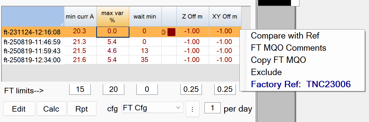
First check the Factory Ref FT: Attach the FactoryReference site (if not already attached). The site may already have a Factory Ref FT imported (has a black square symbol prefixed to its name). If a Factory Ref FT is showing, hover over it to display its initialized serial number as shown here.

If the serial number is correct for the platform that will be collecting data, then you already have the correct Factory Ref FT. Note that the serial number will also appear on the menu, when selecting the Factory Ref FT in the MQO tab as shown here:

If your project does not have an initialized Factory Ref FT with the correct serial number, download the correct one using the link provided in your project startup email. Also, in the BTField project, delete any existing Factory Ref FTs that do not have the correct serial number for the upcoming deployment (or have no serial number). Use the pwd b4n@@m8^K for the deletion.
To import the Factory Ref FT, right click on the FactoryReference site and select Import Surveys. You will be prompted to confirm the serial number as shown here:

Import MQO: If you don’t have the MQO imported yet, create a Site named Setup and attach it. Download the Setup MQO using the link provided in your project startup email. Import it into the Setup site by clicking Import MQO off the Setup site as shown here:

The MQO limits and FT configuration will now automatically appear for all sites attached to the project. You may need to select the FT configuration from the dropdown list in the MQO tab.
The figure below shows the typical MQO settings in the FT limits boxes in BTField. The factory reference FT is selected (orange highlight) in preparation for the user hitting the Calc button to perform MQO validation of each FT against the factory reference FT.
Note: The selected factory ref should have a serial number (TNCxxxxx) that matches the serial number of the platform that collected the data.
FT limits–> - Recommended Defaults.
-
min curr A: The minimum allowable current.
The default setting of 15 Amps is recommended -
max var %: The maximum allowed Rx sensor response variation.
The default of 20 % is recommended -
wait min: The maximum time allowed between MQO validations using the Calc button.
The default of 0 is recommended.This will force the MQO validation to ignore the wait time. -
Z Off m: The maximum vertical offset allowed.
The default setting of 0.25 m is recommended. This setting will only be validated if the field operator decided to add a positional check to the collected FT. -
XY Off m: The maximum horizontal offset allowed.
The default setting of 0.25 m is recommended. This setting will only be validated if the field operator decided to add a positional check to the collected FT. -
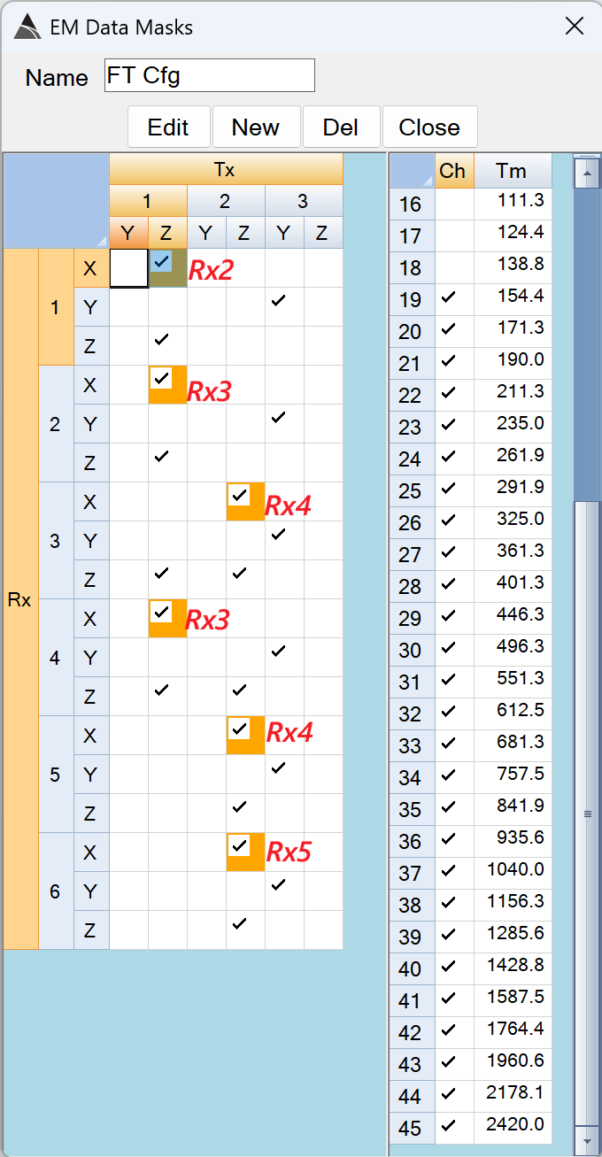
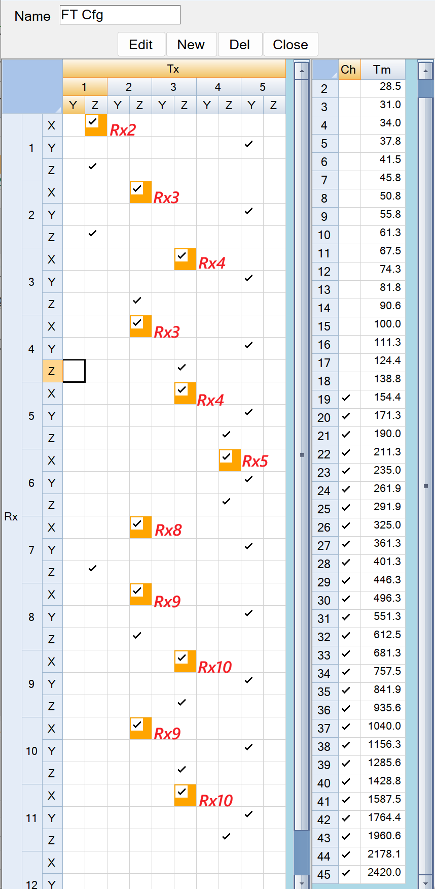
cfg - FT Cfg: A mask that selects the well-coupled Tx-Rx pairs used for the % variation calculations. The default settings for the UltraTEM Portable Classifier and the 5Tx Towed Array Classifier are shown in the figures below. The orange backgounds on some of the selected Tx-Rx pairs indicate an alterative placement location for the test item. For example, in the FT Cfg below, the Tx1.Z - Rx1.X pair is checked and has an orange backgound because the X loop of Rx1 can be illuminated better when the test item is placed on Rx2 (as shown with the red Rx2 label beside it). These masks are pre-set by Black Tusk and should not need to be adjusted.
Processing - P Flow1
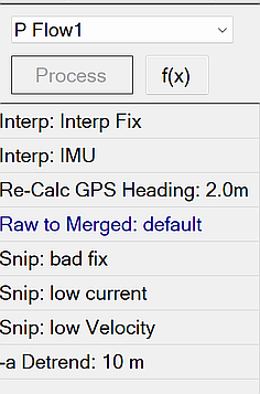
The P Flow1 performs cleaning of out-of-spec data according to the requirements of typical project QAPPs, as well as merging and detrending the data. The figure below shows a typical P Flow1 in BTField:
Interp Fix
Interpolates GPS channels wherever fix quality falls outside of the specified range. The interpolation is performed over a maximum specified distance:
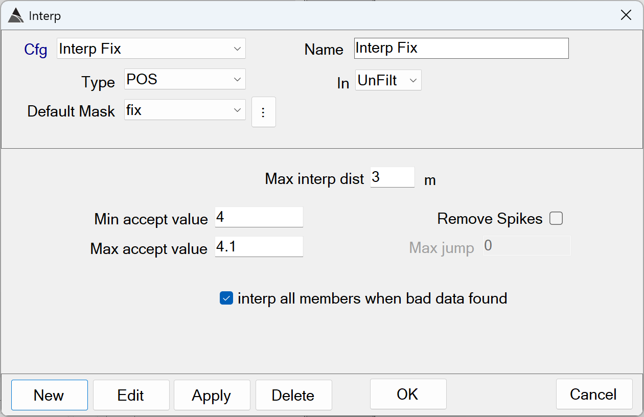
Interp Fix - Recommended Defaults
-
Name: Use a name that best describes the operation.
-
Type: Select the POS type because the Fix data member is found within it.
-
Default Mask: Select the Fix data member.
-
In: Specifies the data state to operate on. Typically the Fix Interp function operates on the UnFilt data state, before the data has been merged in the Raw to Merged step of the flow.
-
Max interp dist: Specifies the maximum distance to interpolate out of range Fix values. Values that are out of range beyond this distance are not interpolated and are left in the data.
The default of 3.0 m is recommendedUsing larger distances may hide areas that likely have poor positioning. -
Min/Max accept value: Together these values define the range of acceptable Fix values in the data. Values outside of this range are interpolated up-to the Max interp dist.
The defaults of *Min* = 4.0 and *Max* = 4.1 are recommended. Using values outside this range risks including poorly positioned data in the processed survey. -
Remove Spikes / Max jump: Enabling the Remove Spikes allows this function to detect jumps or changes in the sequential data of a channel beyond the Max jump threshold. This function is not enabled by default, and it is typically not used for Fix data.
-
interp all members when bad data found: This setting will apply the interpolation to all members of the POS type. For example, if out-of-spec Fix data is found, the interpolation will also be applied to the Easting, Northing and Elevation channels.
The default of ON is recommendedfor any Interp Fix functions.
Interp IMU
Removes spikes and interpolates Pitch, Yaw and Roll channels wherever Max jump is exceeded. The interpolation is performed over a maximum specified distance:
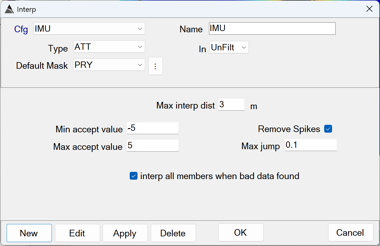
Interp IMU - Recommended Defaults
-
Name: Use a name that best describes the operation.
-
Type: Select the ATT type because the Pitch, Roll and Yaw (PRY) data members are found within it.
-
Default Mask: Select the Pitch, Roll and Yaw (PRY) data members.
-
In: Specifies the data state to operate on. Typically the IMU Interp function operates on the UnFilt data state, before the data has been merged in the Raw to Merged step of the flow.
-
Max interp dist: Specifies the maximum distance to interpolate out of range PRY values. Values that are out of range beyond this distance are not interpolated and are left in the data.
The default of 3.0 m is recommendedUsing larger distances may hide areas that likely have poor positioning. -
Min/Max accept value: Together these values define the range of acceptable PRY values in the data. Values outside of this range are interpolated up-to the Max interp dist.
The defaults of *Min* = -5.0 and *Max* = 5.0 radians are recommended. Using values outside this range risks including poorly positioned data in the processed survey. -
Remove Spikes / Max jump: Enabling the Remove Spikes allows this function to detect jumps or changes in the sequential data of a channel beyond the Max jump threshold. This setting is typically enabled for the Interp IMU function, with a
recommended *Max jump* default of 0.1 radians. Using a lower Max jump may result in interpolating over valid PRY data. Using a higher Max jump may result in leaving PRY spikes in the processed data. -
interp all members when bad data found: This setting will apply the interpolation to all members of the ATT type. For example, if out-of-spec Roll data is found, the interpolation will also be applied to the Pitch and Yaw channels.
The default of ON is recommendedfor any Interp IMU functions.
Re-Calc GPS Heading
Fixes GPS heading flips when the platform has little or no forward motion:
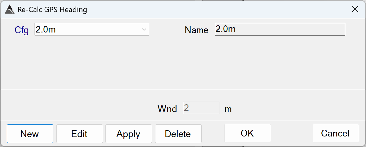
Re-Calc GPS Heading - Recommended Defaults
- Name: Use a name that best describes the operation.
- Wnd: The length (meters) of the window used for the heading calcuation.
The default of 2.0 m is recommended. Using a shorter window length will risk calculating erratic heading values. Using a longer window length will risk calculating heading values that are unresponsive to actual movement of the platform.
Raw to Merged
Merges all raw data to the time base of the EM sensors:
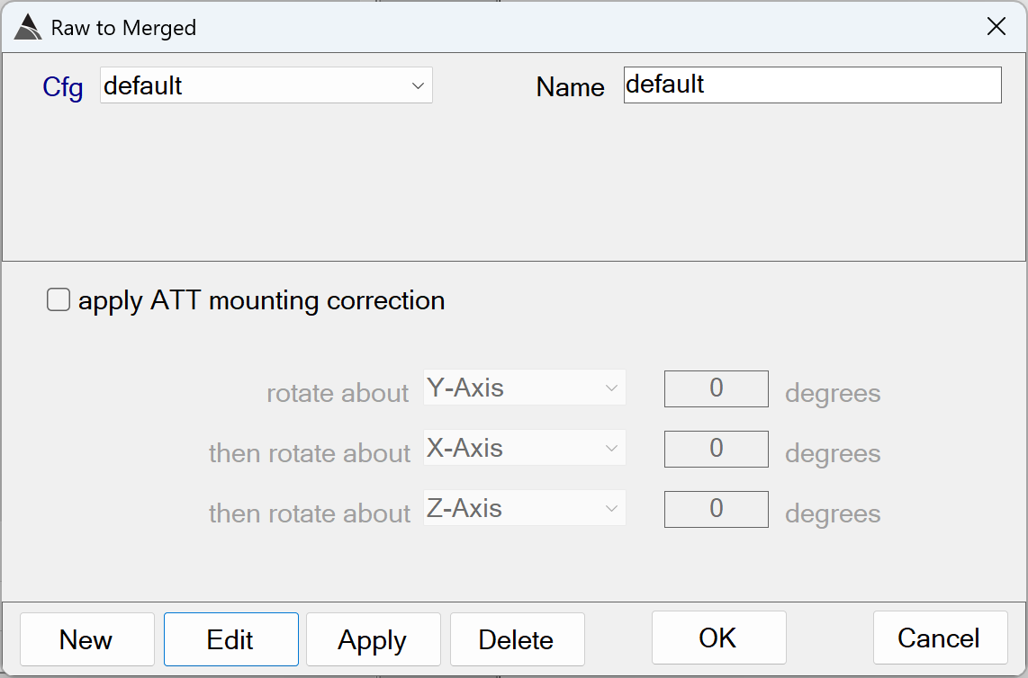
Raw to Merged - Recommended Defaults
- Name: Use a name that best describes the operation.
- apply ATT mounting correction: The option to apply a mounting correction for the ATT data is only used in rare cases when the ATT sensor has been mounted incorrectly.
Snip bad fix
Snips all data outside of the fix quality range of 4.0 to 4.1. This removes all data that could not be interpolated in step 1, due to the maximum range of 3 meters constraint:
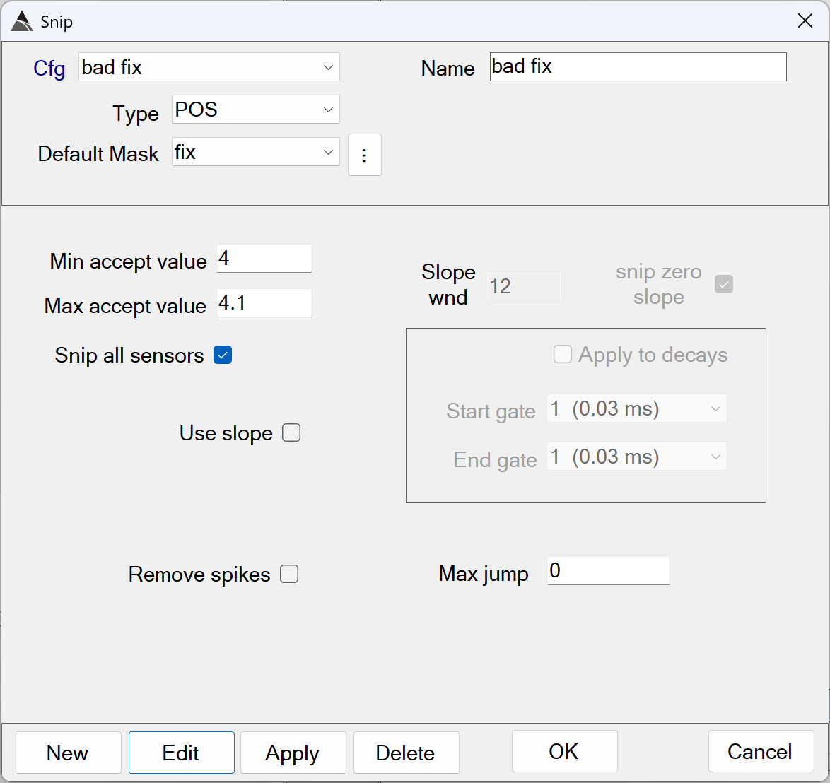
Snip bad fix - Recommended Defaults
-
Name: Use a name that best describes the operation.
-
Type: Select the POS type because the Fix data member is found within it.
-
Default Mask: Select the Fix data member.
-
Min/Max accept value: Together these values define the range of acceptable Fix values in the data. Fix values found outside this range are snipped from the processed data.
The defaults of *Min* = 4.0 and *Max* = 4.1 are recommended. Using a different range risks including poorly positioned data in the processed survey. -
Snip all sensors: This setting will apply the snip to all sensors (all data). For example, if out-of-spec Fix data is found, the snip will be applied to all data types and their members.
The default of ON is recommendedfor any Snip Fix functions. -
Use slope: When selected all the Min / Max accept values will apply to the value of the slope of the data. This option is typically not used when snipping bad fix data.
-
Slope wnd: The length of a moving window that will calculate the slope. This option is typically not used when snipping bad fix data.
-
snip zero slope: This gives the user the option to ignore zero slopes when detecting bad decays. This option is typically not used when snipping bad fix data.
-
Apply to decays: This option applies only to Rx data, therefore it is not used when snipping bad fix data.
-
Remove spikes: Remove spikes that exceed the Max jump value. This option is typically not used when snipping bad fix data.
-
Max jump: Threshold for the Remove spikes. This option is typically not used when snipping bad fix data.
Snip low current
Snips all data below a transmitter current threshold:
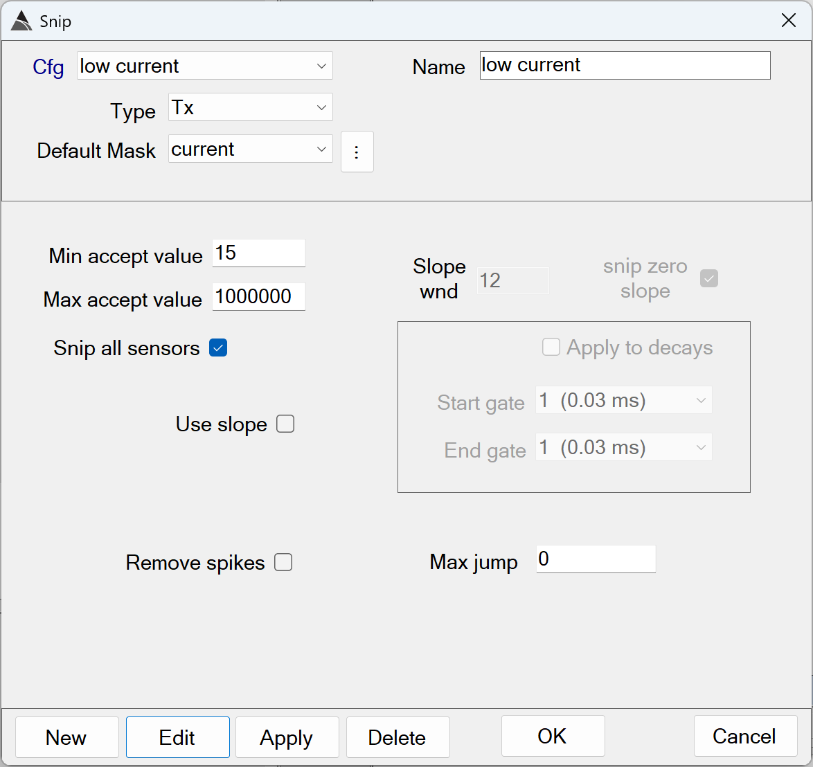
Snip low current - Recommended Defaults
-
Name: Use a name that best describes the operation.
-
Type: Select the Tx type because the Current data members are found within it.
-
Default Mask: Select all Tx Current data members.
-
Min/Max accept value: Together these values define the range of acceptable Tx Current values in the data. Values outside this range are snipped from the processed data.
The defaults of *Min* = 15 and *Max* = 1000000 Amps are recommended. Using a Min less than 15 Amps risks including poorly illuminated anomalies in the processed survey. -
Use slope: When selected all the Min / Max accept values will apply to the value of the slope of the data. This option is typically not used when snipping low current.
-
Slope wnd: When selected all the Min / Max accept values will apply to the value of the slope of the data. This option is typically not used when snipping low current.
-
snip zero slope: This gives the user the option to ignore zero slopes. This option is typically not used when snipping low current.
-
Apply to decays: This option is not used when snipping low current.
-
Remove spikes: Remove spikes that exceed the Max jump value. This option is typically not used when snipping low current.
-
Max jump: Threshold for the Remove spikes. This option is typically not used when snipping low current.
Snip low velocity
Snips all data outside an acceptable velocity range:
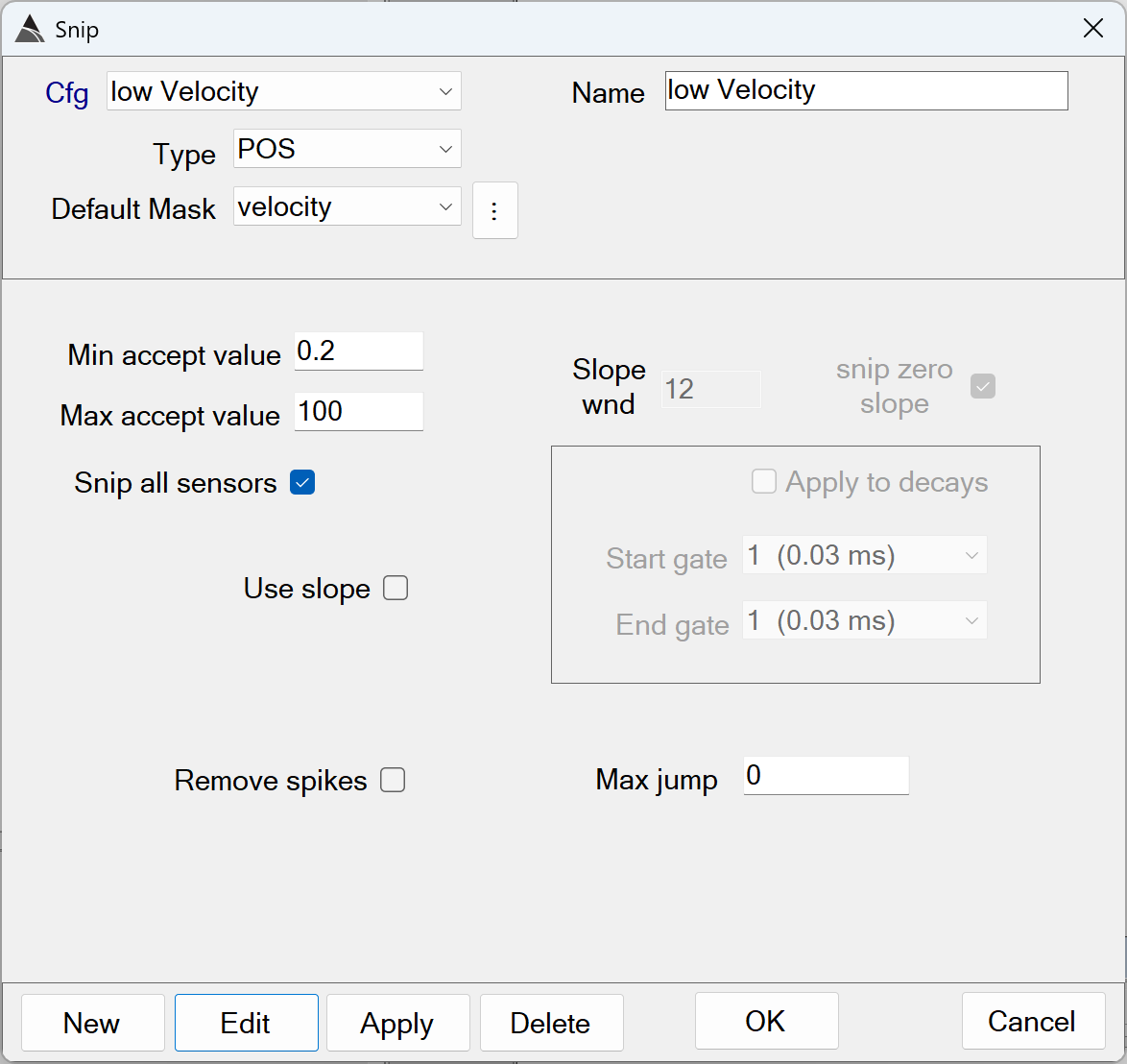
Snip low velocity - Recommended Defaults
-
Name: Use a name that best describes the operation.
-
Type: Select the POS type because the Velocity data member is found within it.
-
Default Mask: Select the Velocity data member.
-
Min/Max accept value: Together these values define the range of acceptable Velocity values in the data. Values found outside this range are snipped from the processed data.
The defaults of *Min* = 0.2 and *Max* = 100 m/s are recommended. Using a Min less than 0.2 m/s risks calculating erratic GPS heading data in the processed survey. -
Use slope: When selected all the Min / Max accept values will apply to the value of the slope of the data. This option is typically not used when snipping low velocity.
-
Slope wnd: When selected all the Min / Max accept values will apply to the value of the slope of the data. This option is typically not used when snipping low velocity.
-
snip zero slope: This gives the user the option to ignore zero slopes. This option is typically not used when snipping low velocity.
-
Apply to decays: This option is not used when snipping low velocity.
-
Remove spikes: Remove spikes that exceed the Max jump value. This option is typically not used when snipping low velocity.
-
Max jump: Threshold for the Remove spikes. This option is typically not used when snipping low velocity.
Detrend
This function applies a standard de-median filter to the Rx type data. A background is estimated by computing the median over a time window, while rejecting data outside of the upper/lower cutoffs. The user has the option to filter all lines or a subset of lines. When filtering a subset of lines, it is recommended to create an additional detrend function in the flow.:
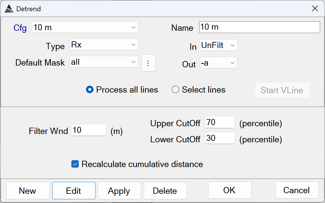
Detrend - Recommended Defaults
-
Name: Use a name that best describes the operation.
-
Type: Select the Rx type because all Tx-Rx pairs and time gate members are found within it.
-
Default Mask: Select the all data mask to detrend all Rx data.
-
In: Specify a named data state to detrend. Typically we detrend the unfilt data state.
-
Out: Specify a named data state to assign the result to. Typically we assign the result of the detrend filter to the -a data state.
-
Process all lines / Select lines: Configure this function to apply filtering to all lines or a subset of lines.
The default ofProcess all linesis recommended. -
Filter Wnd: The length (m) of the moving window used to estimate the background.
The default of 10 m is recommended. Using shorter window lengths in dense areas will risk inclusion of actual anomaly response in the background estimation. Using longer window lengths will lead to unnecessarily long execution times. -
Upper CutOff: The upper percentile cut-off to exclude data from being used to compute the median background for the window.
The default of 70% is recommended. -
Lower CutOff: The lower percentile cutt-off to exclude data from being used to compute the median background for the window.
The default of 30% is recommended. -
Recalculate cumulative distance: Option to re-calculate the cumulative distance. It is recommended to enable this option.
The default of ON is recommended.
Target Picking - Auto-Pick Flow
The figure below shows a typical Auto-Pick flow in BTField:
Detect Targ
This function performs standard threshold target picking using the Blakely Peak Detector Algorithm (Blakely, 1986):
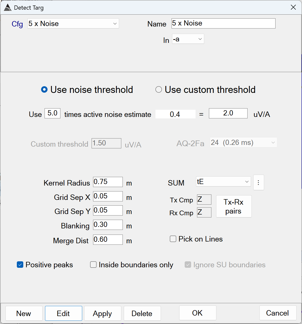
Detect Targ - Recommended Defaults
-
Name: Use a name that best describes the operation.
-
In: The input data state for target picking. This is typically set to the -a data state that has been detrended.
-
Use noise threshold: When selected, this option will extract the noise estimate from the active noise polygon, then multiply it by the Noise scalar value to determine the detection threshold.
The default of ON is recommended. -
Noise scalar: The default is 5.0 times the active noise estimate. This will auto-calculate the detect threshold uV/A.
The default of 5.0 is recommended. Values as high as 10.0 may be used in higher background response areas. Values higher than 10.0 risk missing targets of interest (TOI). Setting values lower than 5.0 will typically detect an unnecessarily large number of targets. -
Use custom threshold: When selected, this option will set the detect threshold directly, and ignore the active noise estimate. To determine the appropriate threshold, it is recommended that a Detection Modeller View be inserted into the BTField project and then used to determine a worst-case detection threshold for the required detection depth of the smallest TOI at the site.
-
Kernal Radius: Defines the circular area around the evaluation point where a 2D peak must be present in the data.
The default of 0.75 m is recommended. Using larger values will risk under-picking (with longer processing times). Using smaller values will risk over-picking. -
Grid Sep X: The easting resolution of the grid (i.e. the distance in meters of one grid pixel in the easting direction).
The default of 0.05 m is recommended. Using larger values will risk missing small TOI. Using smaller values will lead to unnecessarily long processing times. -
Grid Sep Y: The northing resolution of the grid (i.e. the distance in meters of one grid pixel in the northing direction).
The default of 0.05 m is recommended. Using larger values will risk missing small TOI. Using smaller values will lead to unnecessarily long processing times. -
Blanking: The max distance to grid beyond the collected data.
The default of 0.30 m is recommended. -
Merge Dist: The distance between two or more targets where a decision is made to select only the target with the highest peak amplitude.
The default of 0.60 m is recommended. Using smaller values may generate more picks. Using larger values will risk missing TOI. -
SUM: The mask indicating the range of time channels that will be summed and used to create the grid for the target detection. This is typically set to a mid-range of time gates (from 400 us to 850 us). Using an earlier range will risk including saturated responses. Using a later range will risk a loss of response in the generated grid used for the target detection.
-
Tx-Rx pairs: This button will display a top-down view of the platform and allow the user to select the Tx-Rx pairs used to create the grid for the target detection.
-
Pick on Lines: An option to pick target along the Rx profile lines only (i.e. a grid is not used for the target detection).
-
Positive peaks: When enabled, positive peaks are detected.
The default of ON is recommended. -
Inside boundaries only: When enabled, targets will only be detected inside the site’s boundary inclusion polygons.
The default of OFF is recommended. -
Ignore SU boundaries: When enabled, Survey Unit (SU) boundaries will be ignored during the target detection.
The default of OFF is recommended.
Inversion - Auto-Invert Flow
The figure below shows a typical Auto-Invert flow in BTField:
Cell Extract
This function creates (or re-uses) a circular cell around each target and extracts data for inversion:
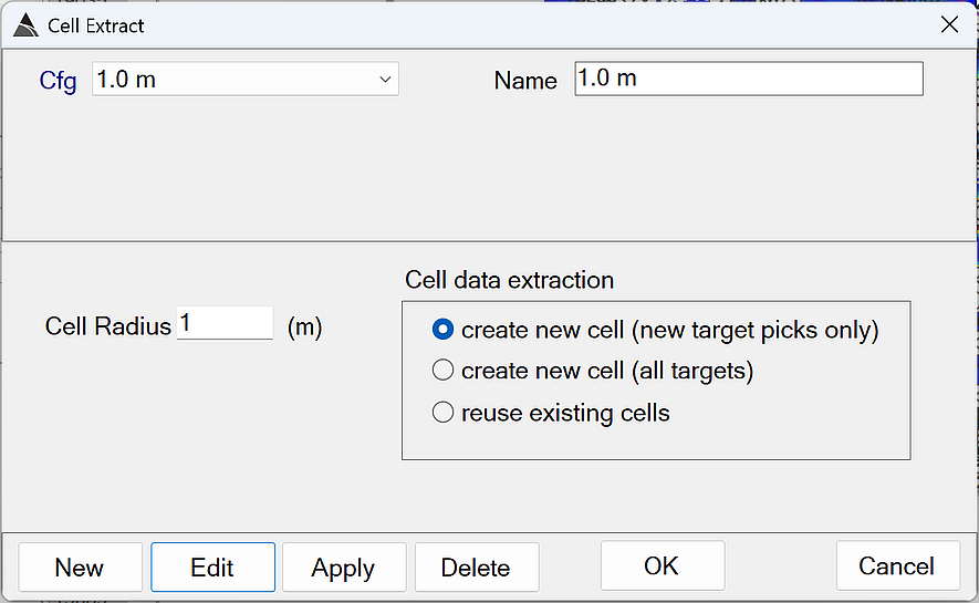
Cell Extract - Recommended Defaults
-
Name: Use a name that best describes the operation.
-
Cell Radius: Defines the circular area around the target where data will be extracted for inversion.
-
create new cell (new target picks only): Option to create new cells only for newly picked targets (i.e. targets that do not have an existing cell yet).
-
create new cell (all targets): Option to create new cells for all targets, regardless of whether they have an existing cell.
-
reuse existing cells: Option to re-use existing cells only.
EM Invert
This function creates (or re-uses) a circular cell around each target and extracts data for inversion:
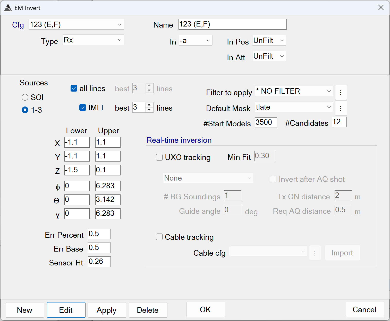
EM Invert - Recommended Defaults
-
Name: Use a name that best describes the operation.
-
Type: Select the Rx data type.
-
In: Specifies the data state to operate on. Typically the EM Invert function operates on the -a data state in post-processing.
-
In Pos: Specifies the POS data state to use for the inversion. Typically the EM Invert function uses the unfilt POS data state in post-processing.
-
In Att: Specifies the ATT data state to use for the inversion. Typically the EM Invert function uses the unfilt ATT data state in post-processing.
-
SOI: Option to perform a Single Object Inversion (SOI) only.
-
1-3: Option to perform an SOI, 2OI, and 3OI inversion. This generates a total of six sets of polarizabilities.
The default of ON is recommended. -
all lines: Option to include all vehicle lines that pass through the cell being inverted.
The default of ON is recommended -
best N lines: Option to select only the best N vehicle lines for the regular inversions. The best lines are determined by their coverage around the target pick location. This option is only enabled when all lines is OFF.
-
IMLI: Option to perform Independent Model Location Inversions (IMLI), in addition to the regular inversions.
The default of ON is recommended. -
IMLI best N lines: Option to select only the best N vehicle lines for the IMLI inversions. The best lines are determined by their coverage around the target pick location.
The default of 3 lines is recommended. Using fewer lines may not take advantage of additional data providing good coverage over the anomaly. Using more lines will lead to unnecessarily longer inversion times. -
Filter to apply: Option to apply a query filter to invert only specific cells when the reuse exisiting cells option is enabled in the preceding Cell Extract function in the flow. Typically, a filter is not used.
The default of NO FILTER is recommended. -
Default Mask: A mask that selects the Tx-Rx pairs and time gates for the inversion. Typically all Tx-Rx pairs are selected. Also, the first time gate is typically selected at 260 us, with all later time gates selected. Selecting earlier time gates risks inversion of saturated data.
-
#Start Models: For multi-source inversion (option 1-3) there is a preliminary scan for start models.
The default of 3500 is recommended. -
#Candidates: The number of best-fit models to retain after the preliminary scan. These models will be fitted further in the optimization solver.
The default of 12 is recommended -
X Lower-Upper: Specifies the lower and upper X bounds of the inversion, relative to the target pick location.
The defaults of -1.1 m and 1.1 m are recommended. -
Y Lower-Upper: Specifies the lower and upper Y bounds of the inversion, relative to the target pick location.
The defaults of -1.1 m and 1.1 m are recommended. -
Z Lower-Upper: Specifies the lower and upper Z bounds of the inversion, relative to the target pick location.
The defaults of -1.5 m and 0.1 m are recommended. -
ɸ Lower-Upper: Specifies the lower and upper azimuth bounds of the inversion.
The defaults of 0 and 6.28 radians are recommended. -
ϴ Lower-Upper: Specifies the lower and upper dip angle bounds of the inversion, relative to vertical.
The defaults of 0 and 3.14 radians are recommended. -
ɣ Lower-Upper: Specifies the lower and upper rotation bounds of the inversion.
The defaults of 0 and 6.28 radians are recommended.
MQO - Validation of IVS Surveys
IVS Surveys .
The figure below shows the typical MQO settings in the Survey limits boxes in BTField. The IVS survey is selected (orange highlight) in preparation for the user hitting the Calc button to perform MQO validation.
Note: The IVS survey in this example has already been processed by the P Flow1. It has also been seeded with ground truth locations using the targ/seeds configurator, and inverted using the Auto-Invert flow.
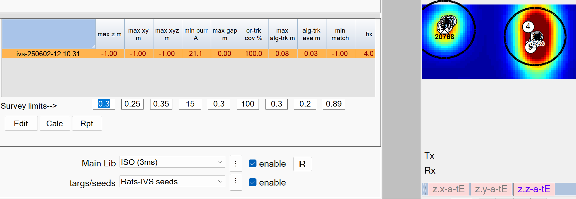
Survey limits–> - Recommended Defaults.
-
max z m: The maximum allowable vertical (Z) error from the ground truth position.
The default setting of 0.3 m is recommended -
max xy m: The maximum allowable horizontal (XY) error from the ground truth position.
The default setting of 0.25 m is recommended -
max xyz m: The maximum allowable distance (XYZ) error from the ground truth position.
The default setting of 0.35 m is recommended -
min curr A: The minimum allowable Tx current.
The default setting of 15 Amps is recommended -
max gap m: The maximum allowable cross-track gap.
The default setting of 0.3 m is recommended -
cr-trk cov %: The minimum allowable cross-track coverage. This reports the percentage of the site polygon that meets data coverage MQOs.
The default setting of 100 % is recommended -
max alg-trk m: The maximum allowable along-track gap between sequential observations of an Rx sensor.
The default setting of 0.3 m is recommended -
alg-trk ave m: The maximum allowable along-track average gap.
The default setting of 0.2 m is recommended -
min match: The minimum allowable library match using all three polarizabilities (L1,L2,L3)
The default setting of 0.90 % is recommended -
fix: All data is required to have GPS Fix = 4. The MQO calculation will report failed if any values are not 4 or 4.1, where 4.1 indicates that positions have been interpolated.
Informed Source Selection - ISS Flows
The figure below shows the typical ISS flows in BTField. They are always run in succession. The Fail flow is run first, followed by the Select flow, and the Unselect flow is run last:
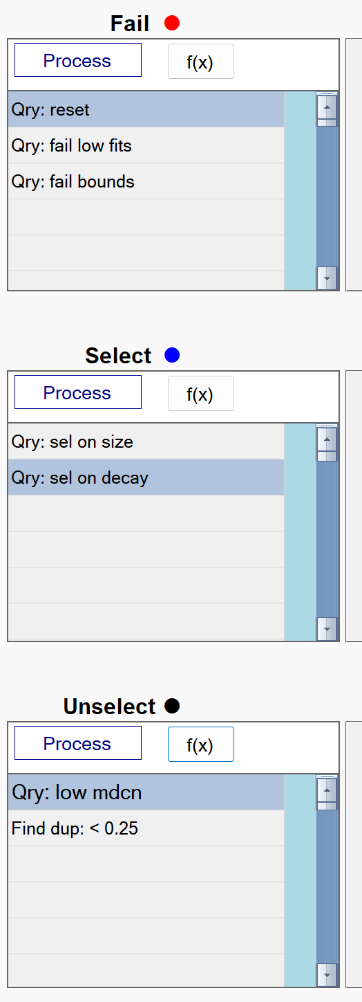
ISS Fail flow
The figure below shows a typical ISS Fail flow in BTField:
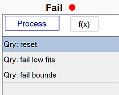
reset
This function resets all status attributes of each source. The figure below shows the reset function with all data fits being captured by the query. All queried sources will have their status cleared since the fail, selected, dig, don’t dig, and flag status members are all unchecked.
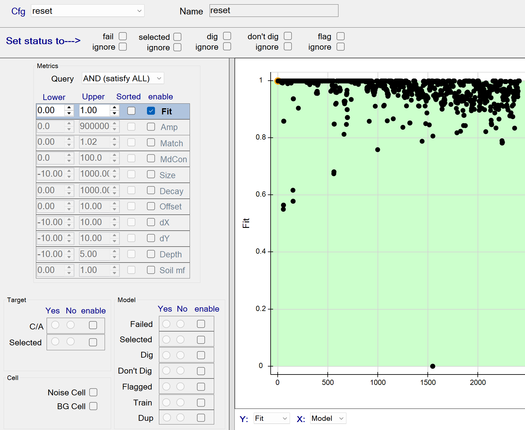
reset - Recommended Defaults
- Recommended defaults are as shown in the figure above.
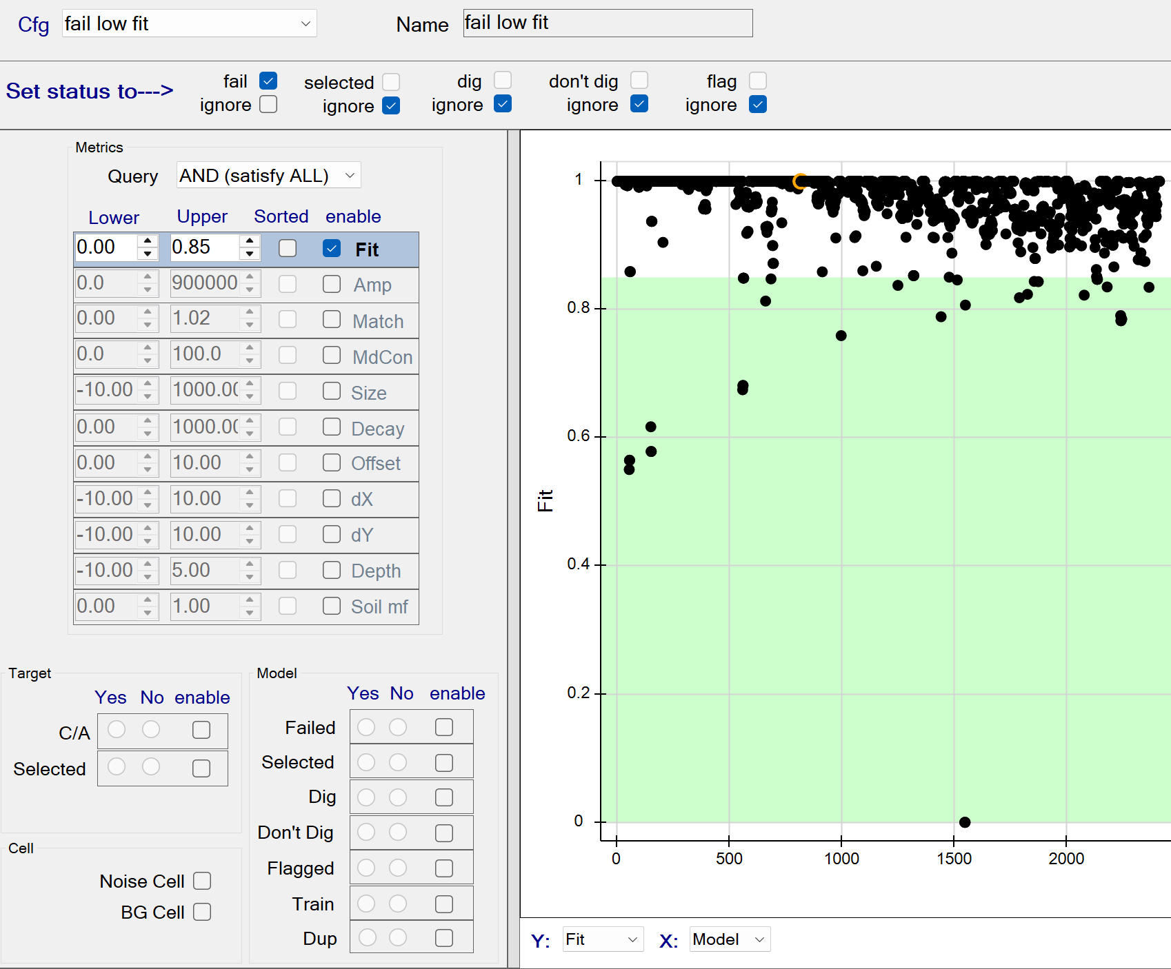
fail low fits
This function fails all sources with a model Data Fit <= 0.85. The figure below shows all data fits <= 0.85 being captured by the query. These queried sources will all be failed since the fail status member is checked.
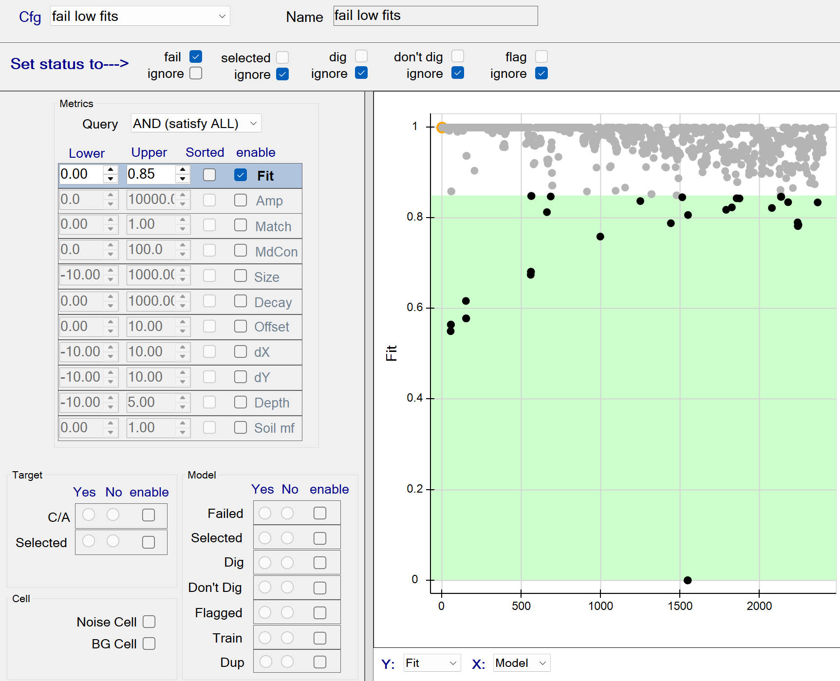
fail low fits - Recommended Defaults
- Recommended defaults are as shown in the figure above.
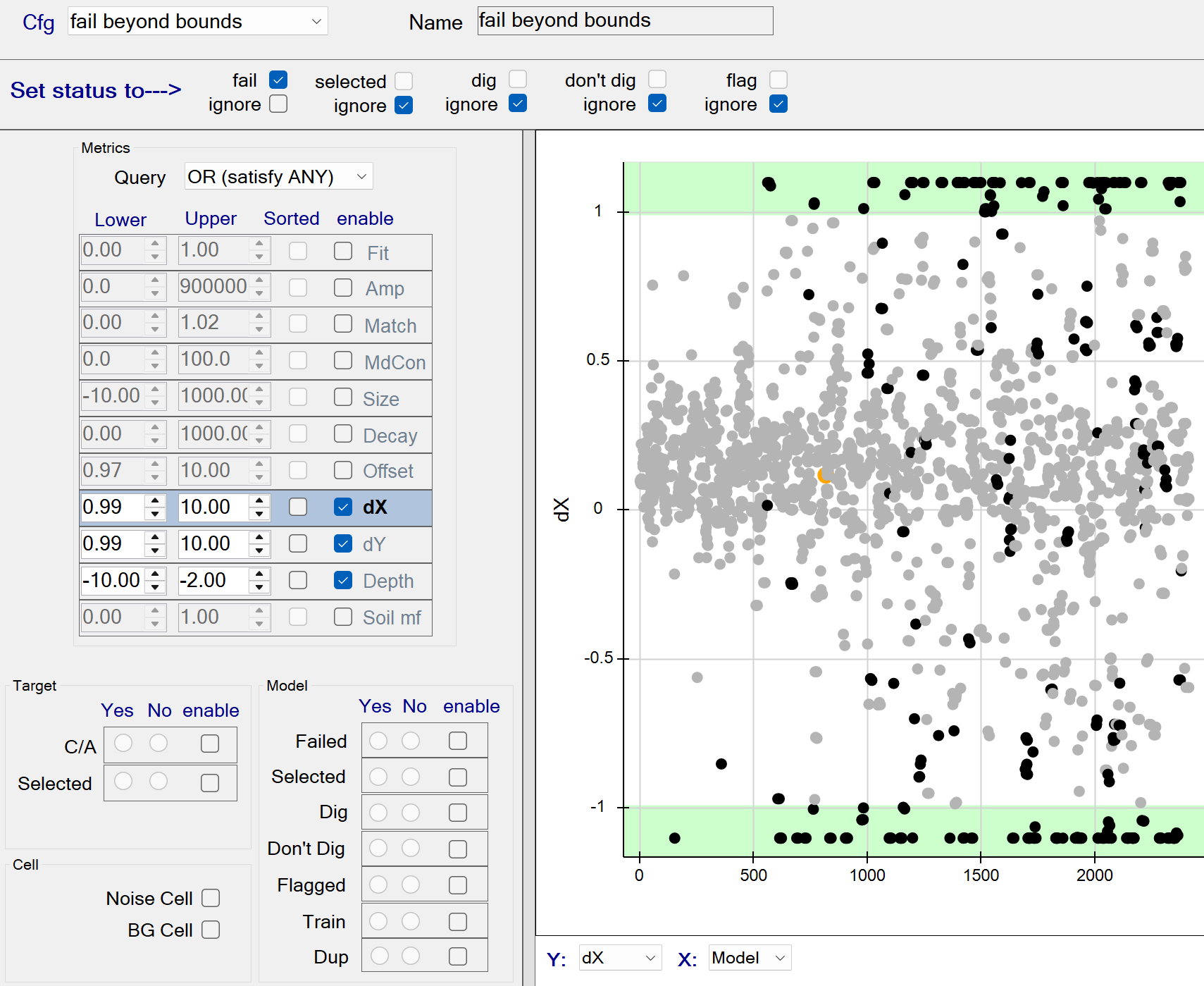
fail bounds
This function fails all sources located at the edge of the inversion bounds. The figure below shows the Query operation set to a boolean OR operation. Therefore all sources having any dx, dy, or Depth beyond the specified bounds will be captured by the query. These queried sources will be failed since the fail status member is checked.
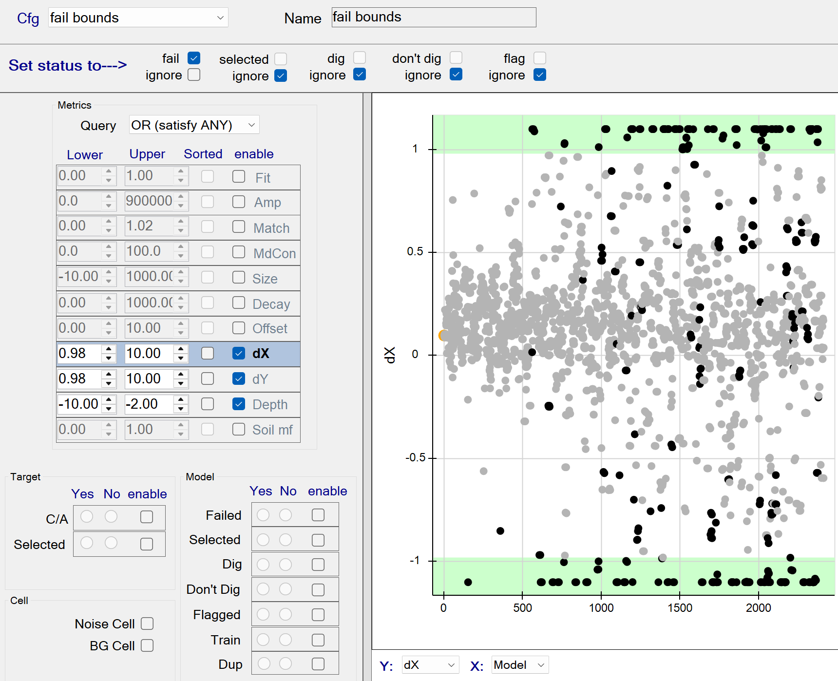
fail bounds - Recommended Defaults
- Recommended defaults are as shown in the figure above.
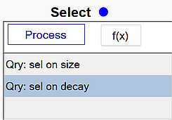
ISS Select flow
The figure below shows a typical ISS Select flow in BTField:
sel on size
This function selects all sources with a Size >= 0.40. The figure below shows all sizes >= 0.45 being captured by the query. These queried sources will all be selected since the selected status member is checked.
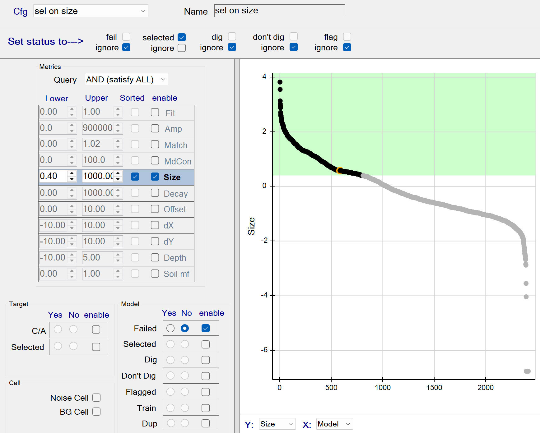
sel on size - Recommended Defaults
- Recommended defaults are as shown in the figure above.
sel on decay
This function selects all sources with a Decay <= 20. The figure below shows all decays <= 20 being captured by the query. These queried sources will all be selected since the selected status member is checked.
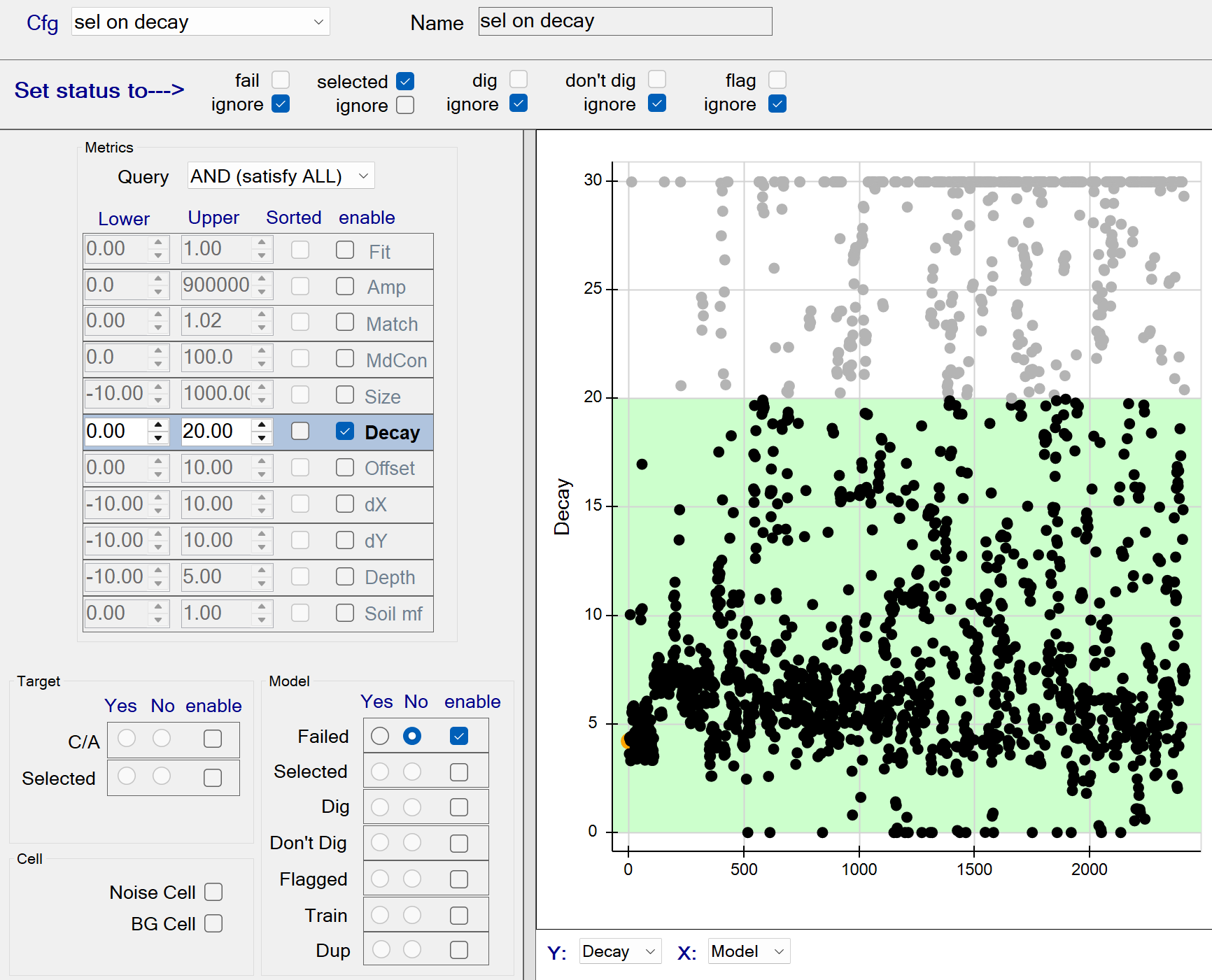
sel on decay - Recommended Defaults
- Recommended defaults are as shown in the figure above.
ISS Unselect flow
The figure below shows a typical ISS Unselect flow in BTField:
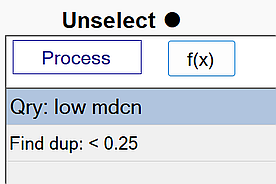
low mdcn
This function unselects sources with a Model Contribution (mdcn) <= 15 as shown in The figure below. Note: the query only operates on sources that are currently selected, since the lower selected option is set to Yes. Therefore all selected sources having mdcn <= 15 are captured by the query. These queried sources will all be unselected since the selected status member (at top) is unchecked.
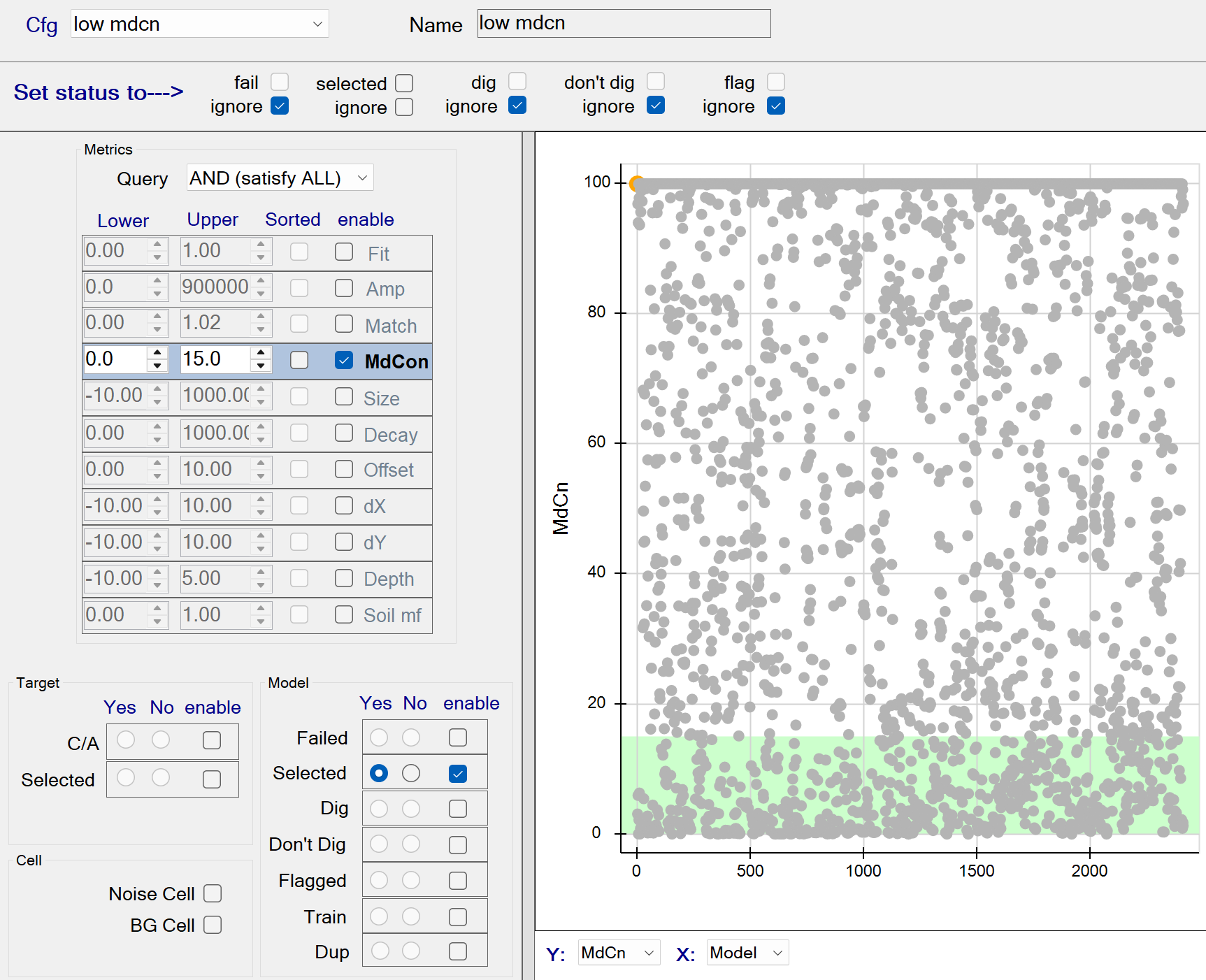
low mdcn - Recommended Defaults
- Recommended defaults are as shown in the figure above.
find dup
This function unselects duplicate sources as shown in the figure below:
find dup - Recommended Defaults
-
Name: Use a name that best describes the operation.
-
Declare as duplicate if similarity is above: Determines how similar the polarizabilities must be before one of the sources can be considered a duplicate.
The default of 0.01 % is recommended. This will force the duplicate check to ignore polarizability similarity. -
AND separation is less than: When two sources are closer together than this value, one of them can be considered to be a duplicate.
The default of 0.25 m is recommended. The source with the lower Data Fit will be declared as the duplicate.
One Pass Flows
The figure below shows the typical One Pass flows in BTField. They are always run in succession. Each successive stage attempts to classify uxo with a more specifically tuned library configuration that will still provide good matching capability against uxo with weak secondary polarizabilities.
Note: Stage 3 is typically not used. It is available to users, but only for rare situations with specific classification challenges.
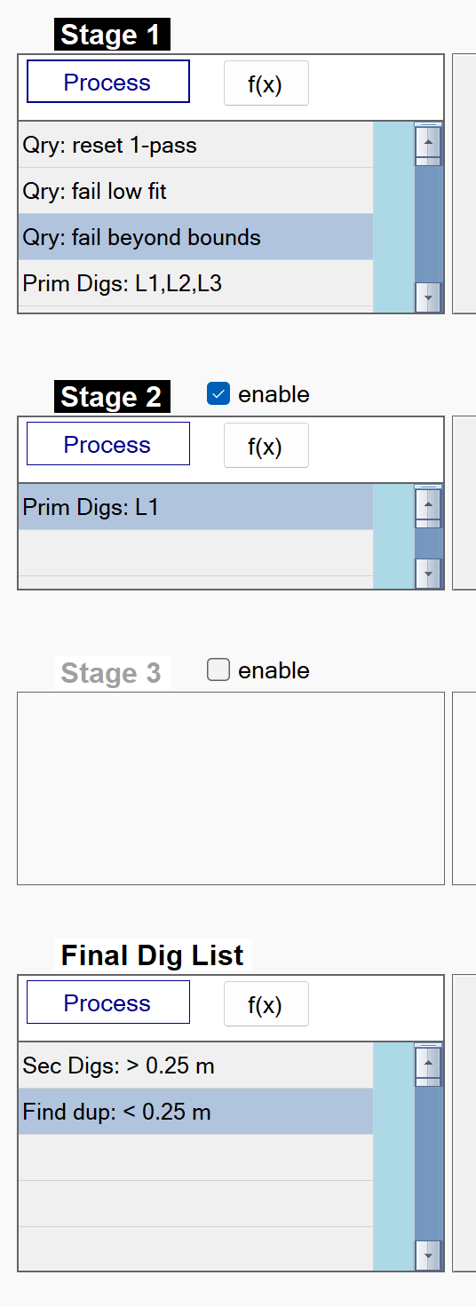
Stage 1 flow
The figure below shows a typical One Pass Stage 1 flow in BTField. :
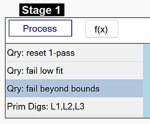
Stage 1: reset 1-pass
This function resets all status attributes of each source. The figure below shows the reset function with all data fits being captured by the query. All queried sources will have their status cleared since the fail, selected, dig, don’t dig, and flag status members (at top) are all unchecked.
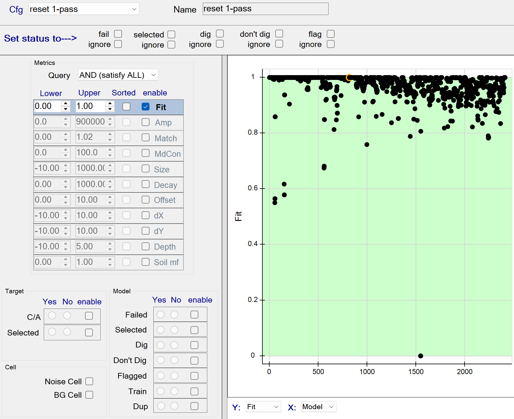
Stage 1: reset 1-pass - Recommended Defaults
- Recommended defaults are as shown in the figure above.
Stage 1: fail low fit
This function fails all sources with a model Data Fit <= 0.85. The figure below shows all sources with data fits <= 0.85 being captured by the query. These queried sources will all be failed since the fail status member (at top) is checked.
Stage 1: fail low fit - Recommended Defaults
- Recommended defaults are as shown in the figure above.
Stage 1: fail beyond bounds
This function fails all sources located at the edge of the inversion bounds. The figure below shows the Query operation set to a boolean OR operation. Therefore all sources having any dx, dy, or Depth beyond the specified bounds will be captured by the query. These queried sources will be failed since the fail status member (at top) is checked.
Stage 1: fail beyond bounds - Recommended Defaults
- Recommended defaults are as shown in the figure above.
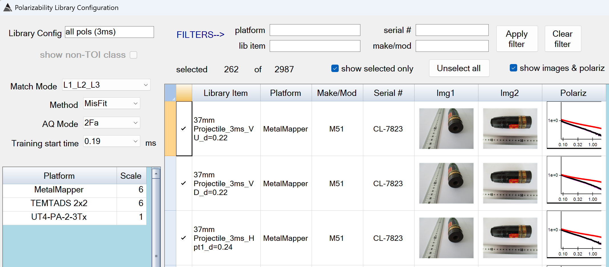
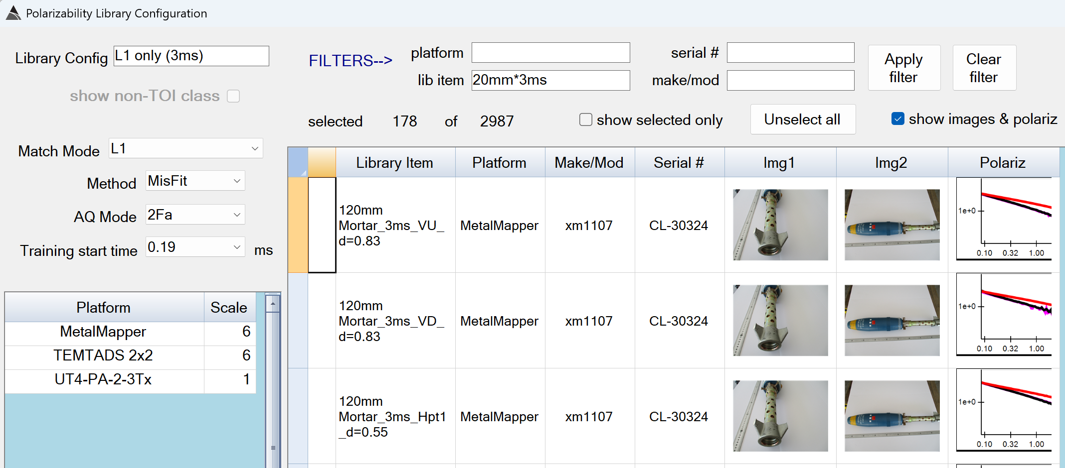
Stage 1: Prim Digs L1,L2,L3
This function finds the best matching library item for each source using all 3 polarizabilities (L1, L2, L3).
Stage 1: Prim Digs - Recommended Defaults
-
Library Config: Use a name that best describes the library matching mode and selected items.
-
Match Mode: Determines which polarizabilities are used for the matching.
The default of L1_L2_L3 is recommended for Stage 1 -
Method:
The default of MisFit is the only available option.` -
AQ Mode: Select the AQ Mode of the surveys you are processing.
-
Training start time: Select the earliest time gate that inversions can use.
The value of 0.19 ms is recommended. -
Platform - Scale: The polarizabilities in the uxo library have been generated from data collected on different sensor platforms, therefore scale factors are needed to align the library polarizabilities with inverted polarizabilities of the processed survey.
The default of 6.17 for MetalMapper and TEMTADS 2x2 is recommended. -
FILTERS–>: Wildcard filters can be set in the platform, lib item, serial#, and make/mod boxes to assist in selecting the appropriate library items for the site requirements. Please ensure your selected items have a similar decay length as your inverted polarizabilities. For example, if your data has been collected in AQ Modes F or E, include a “3ms” filter in the lib item box. If your data has been collected in AQ Modes C or D, include an “8ms” filter in the lib item box.
Stage 2 flow
The figure below shows a typical One Pass Stage 2 flow in BTField. The goal of this flow is to match against uxo that may have been missed in Stage 1. To accomplish this, the library configuration in Stage 2 is tuned to use fewer polarizabilities for matching.:
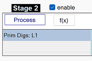
Stage 2: Prim Digs L1
This function finds the best matching library item for each source using only the primary polarizability (L1).
Stage 2: Prim Digs L1 - Recommended Defaults
-
Library Config: Use a name that best describes the library matching mode and selected items.
-
Match Mode: Determines which polarizabilities are used for the matching.
The default of L1 is recommended for Stage 2 -
Method:
The default of MisFit is the only available option.` -
AQ Mode: Select the AQ Mode of the surveys you are processing.
-
Training start time: Select the earliest time gate that inverstions can use.
The value of 0.19 ms is recommended. -
Platform - Scale: The polarizabilities in the uxo library have been generated from data collected on different sensor platforms, therefore scale factors are needed to align the library polarizabilities with inverted polarizabilities of the processed survey.
The default of 6.17 for MetalMapper and TEMTADS 2x2 is recommended. -
FILTERS–>: Wildcard filters can be set in the platform, lib item, serial#, and make/mod boxes to assist in selecting the appropriate library items for the site requirements. Please ensure your selected items have a similar decay length as your inverted polarizabilities. For example, if your data has been collected in AQ Modes F or E, include a “3ms” filter in the lib item box. If your data has been collected in AQ Modes C or D, include an “8ms” filter in the lib item box.
Final Dig List flow
The figure below shows a typical Final Dig List flow in BTField:
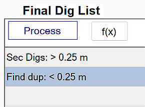
Sec Digs: > 0.25 m
This function adds secondary sources to each stage based on the lock point for that stage.
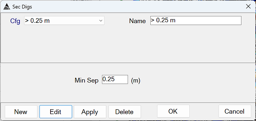
- Min Sep - A non-dig source will become a secondary dig source if its horizontal distance to an existing dig source is greater than Min Sep AND it has a higher library match than the worst matching dig source in the stage.
The default of 0.25 is recommended
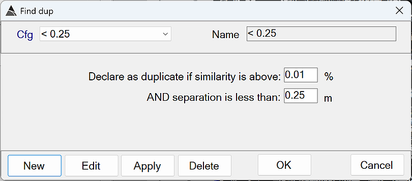
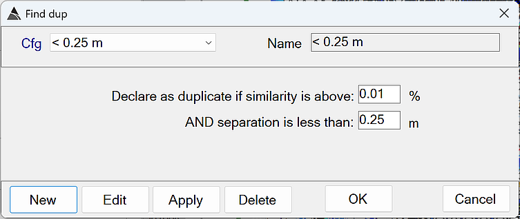
Find Dup: < 0.25 m
This function finds duplicate sources in the dig list.
-
Declare as duplicate if similarity is above: Determines how similar the polarizabilities must be before one of the sources can be considered a duplicate.
The default of 0.01 % is recommended. This will force the duplicate check to ignore polarizability similarity. -
AND separation is less than: An existing dig source will be marked as a duplicate if its horizontal distance to an earlier source in the dig list is less than this value.
The default of 0.25 m is recommended.